Electrical resistivity methods include three-electrode, four-electrode, and multi-electrode techniques. Electrical resistivity for exploration of geologic deposits has been around for quite some time. The technique predates digital computers and relied on Wenner, Schlumberger, and dipole-dipole methods. These methods use 4-electrode configurations to identify layers or anomalies, at depth. In the 1930s, mathematicians such as Langer and Slichter began to work on the problem. Andrey Nikolayevich Tikhonov was key in developing a solution in the form of a 2-layered medium. During the 1940s ERI (Electrical Resistivity Imaging) and ERT were discovered by collaborating geophysicists, famously finding large copper deposits.
When computers became widely available during the 1960s and 1970s numerical solutions became easier to obtain which increased accuracy when interpreting data. These days ERT is still used in its original form, with much thanks to Loke & Barker at Birmingham University who developed one of the first successful numerical approaches to solve the inverse problem of ERT. In general, resistivity measurements work by sending an electrical current into the ground and measuring the resulting voltage along different paths. The data from these measurements can then be used to create one-dimensional, two-dimensional, and three-dimensional color images of the subsurface.
Resistivity is based the fact that electrical current flows more easily through areas of lower resistance than higher resistance.
This technique is based on the principle that electricity will flow more easily through areas of lower resistance than through areas of higher resistance. The electrical current sent into the ground can detect clay deposits and bedrock that may otherwise be difficult to identify. In addition, it can detect potentially hazardous contaminants as well as preferential paths, or voids present within the subsurface environment. All of this information allows engineers to map out a region with greater accuracy to make informed decisions regarding site planning. By applying an electrical current to the ground and measuring the resulting voltage across electrodes placed at fixed distances, it is possible to create a map of the subsurface resistivity. Repeating the Process for various depths and distances along a transect line leads to electrical resistivity imaging or tomography.
ERI techniques inject electrical current into the ground at hundreds of locations and measures the voltage at hundreds or thousands of different distances. ERI or ERT often utilize Wenner, dipole-dipole, Schlumberger configurations. The approach enables the production of a map that displays electrical resistivity in 2-D and/or 3-D. Additionally, Schulmberger and other site-specific configurations may be used, depending on the application and target being surveyed. It is important to keep in mind that the targets must be large enough to detect or map. Similarly, the zones of insterest must have a detectable electrical contrast. Thus, it is essential that any survey comes well-equipped with an appropriate configuration and advanced post-processing techniques.
Resistivity imaging, tomography, and soundings for engineering geophysics
While three and four-electrode electrical resistivity measurements are still readily used in the power industry, ERT has a wide range of applications in engineering geophysics including environmental site characterization, geological studies, groundwater investigations, detecting voids, locating Karst activity, mapping buried private facilities, and searching for preferential paths for fluids to flow. The equipment is relatively portable and easy to use, making it a popular choice for many field engineers. If you’re interested in learning more about ERT or how it can be used in your work as an engineer, read on for a brief overview of the basics.
Methods used in engineering geophysics to create cross-sections of subsurface resistivity.
Electrical resistivity imaging (ERI) is a 2D or 3D geophysical technique used for mapping engineering applications such as depth to bedrock, faulting and fracturing of the subsurface, soil classifications, locating preferential paths for groundwater flow, karst activity, aquifer parameters, and other subsurface features. This method has proven to be successful in identifying voids and fractures as well as mapping non-linear anomalies that could not be identified using conventional surveying methods. ERI provides valuable information in geotechnical investigations since it can predict the subsurface electrical properties that may affect the integrity of a structure or project. Furthermore, its ability to detect subtle changes in electric conductance between different types of materials makes it an invaluable tool for locating where bedrock is likely to contain voids or faults which may result in instability within a structure.
Soundings or 1-D measurements
1D electrical resistivity measurements are of great importance in engineering applications. These basic measurements are often needed for the design of electrical power stations. They also assist with assessing the potential for adverse corrosion, and characterizing secondary porosity caused by the jointing and/or faulting in saturated bedrock. In other words, to properly design and engineer a power station or grounding grid engineers often need to know the electrical resistivities at a single location as a function of depth, often to great depths. In contrast, corrosion studies rely on shallow values of electrical resistivity. The measurements help assess and design cathodic protection systems to minimize corrosion. Last, azimuthal resistivity acquires data by rotating a four-electrode array with fixed spacings around a center point. The result is a presentation that allows one to interpret the orientation and degree of secondary porosity caused by jointing, fracturing, and/or faulting within saturated bedrock.
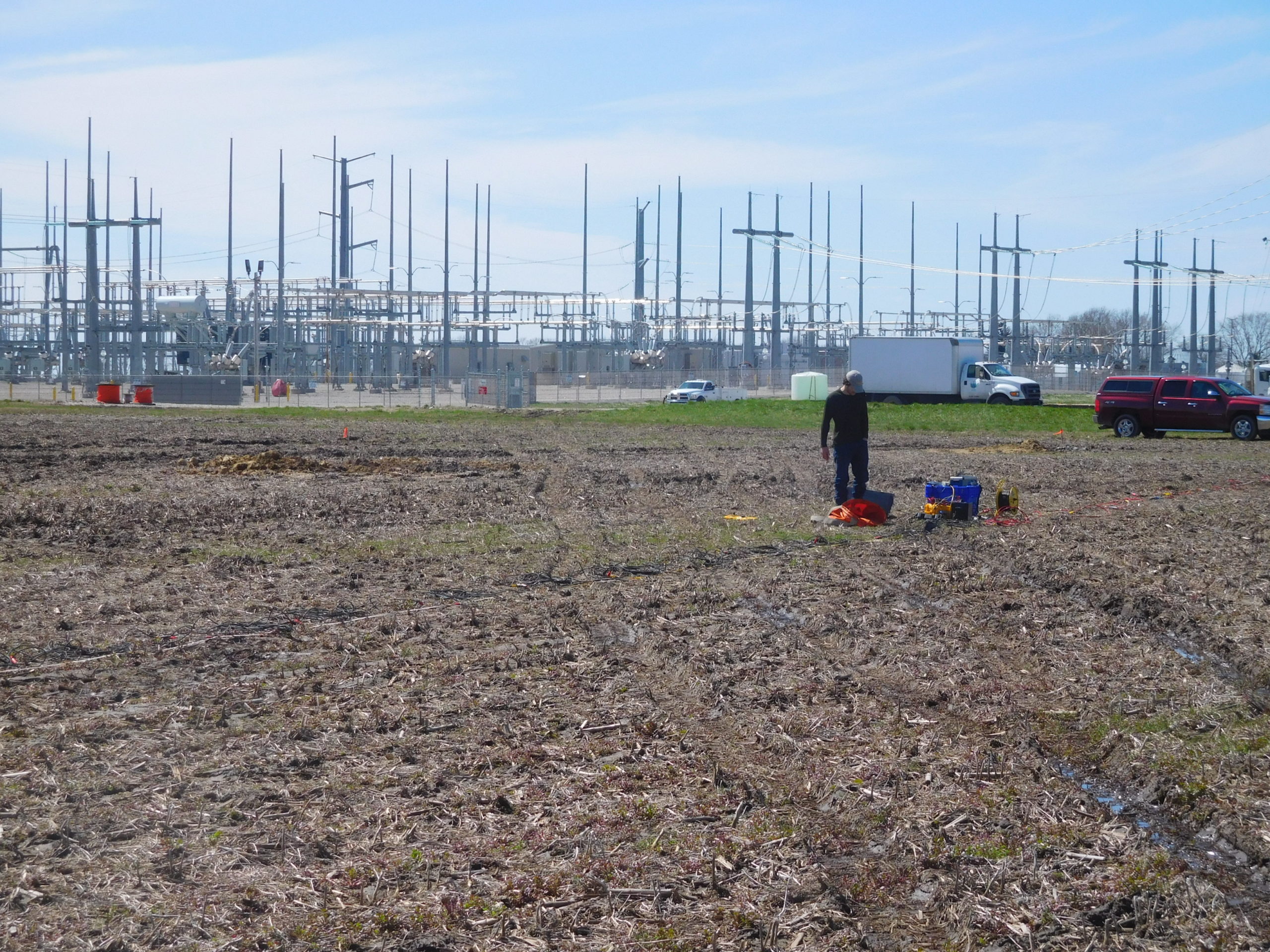
Electrical resistivity soundings are often required for the design or upgrade of a power station. The measurements provide valuable information about the electrical properties of subsurface materials. This allows engineers to determine the suitability of a potential site for the construction of a power station. The ASTM G57 and IEEE 83 standards are two well-established methods for performing electrical resistivity soundings at power station sites. ASTM G57 is a four-electrode field testing method that allows for the determination of subsurface resistivity values at a specific location. The IEEE 83 standard involves measurements made with three-electrode or four-electrode arrays, and is used to measure larger subsurface areas. In both cases, the data collected from the tests can be used to form a resistivity plot of the subsurface. The plot provides valuable information about the geologic and soil conditions at the site.
Summary electrical resistivity methods
ERI is an important tool in engineering geophysics for mapping subsurface features. It has proven to help engineers in selecting the most suitable location for constructing a power station. Engineered designs depend on knowing soil properties, groundwater conditions, and rock type. Consequently, these surveys can help identify possible problems with power line routing. In addition, one can highlight environmentally sensitive areas that need to be avoided. Overall, electrical resistivity soundings are an essential tool in engineering power stations. The assist with ensuring sites are chosen and prepared with all necessary design and safety precautions taken into consideration.
Find Pages On EngineeringGeophysics.com
The equipment used for this method consists of an electrical source, electrodes, and a recording device.
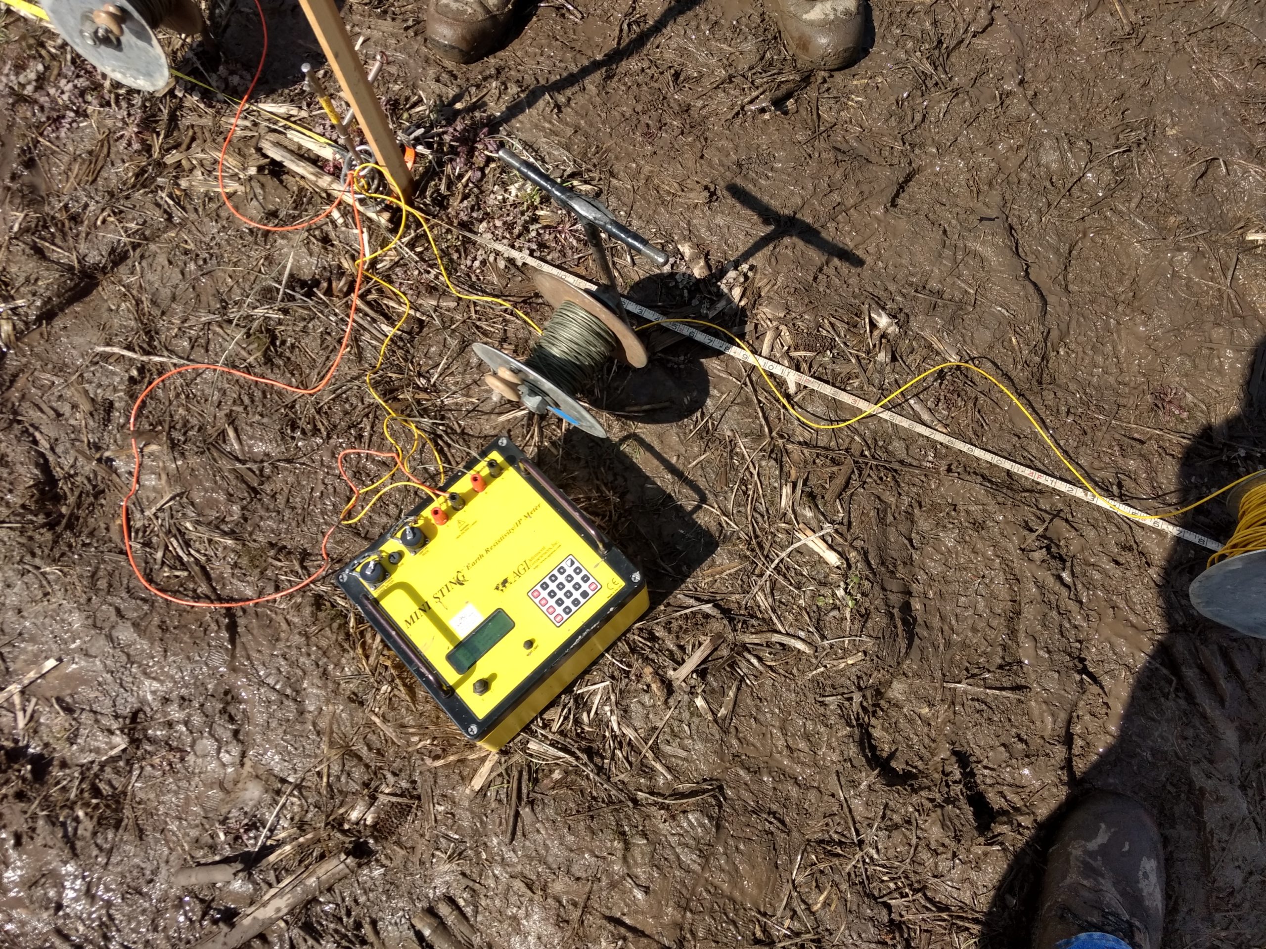
Unlike ERI, three-electrode and four-electrode resistivity measurements require a less sophisticated suite of instrumentation. As the method suggests, one starts with either three or four electrodes, commonly made of stainless steel. Each electrode must have a spool of wire that reach the necessary distances per the survey configuration. The wire connects an electrode to a console. The electrical resistivity counsel injects current into the ground. Without doubt, the console must have the power necessary to respond to the conditions at depth. AGI’s Ministing and Swift councils provide up to 500 mA of current. Their Supersting R8 counsel is capable of 2000 mA. As with all electrical resistivity surveys, a small hammer may be needed to drive electrodes into the ground. Also, do not forget an ample supply of water, which is often needed to reduce contact resistance.
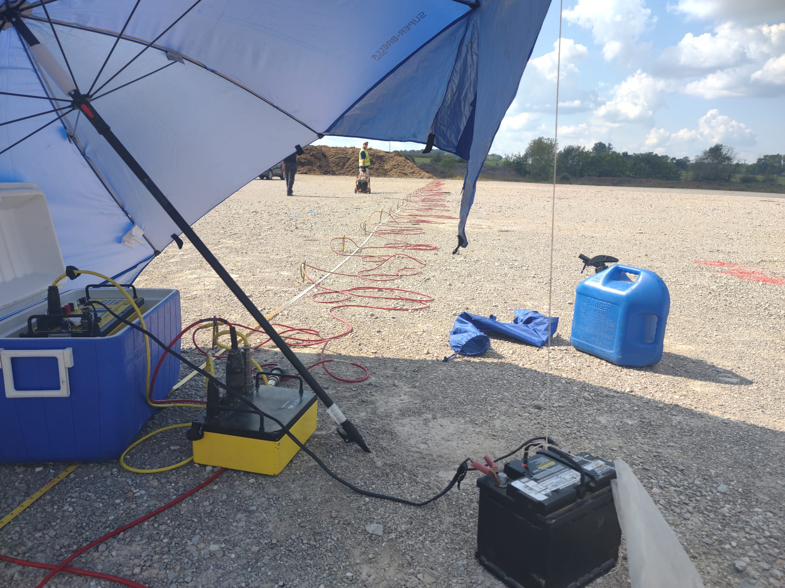
ERI is a versatile geophysical technique and its equipment can vary depending on the application. In engineering geophysics, an AGI Super Sting R8 Console is often used as a transmitter and receiver. Frequently, an array of 84 stainless steel electrodes are connected to the AGI Super Sting with 84 take-out cables. In addition to water and a hammer a large battery or batteries are required because of the large array spacings, . In extreme heat, it is often wise to bring an umbrella to shade the console. Also, one can stand the console in a cooler with shallow water, don’t submerge it. Transmitting high levels of current generally creates heat. The metal case of the console acts like a radiator to dissipate heat into the water. Finally, the AGI Super Sting has built-in memory, a CPU, and the ability to utilize command files. These command files are often site-specific.
Electrical resistivity methods have many applications
By using advanced electrical instrumentation, electrical resistivity cross-sections can be generated to detect or map large features for engineering geophysics. Without doubt, electrical resistivity methods include mapping groundwater resources, assessing environmental contamination, void detection, detecting karst conditions, and locating buried metal objects such as pipelines and cables. This versatile method is also used to predict geological structures such as geologic units, bedding planes, and faulting.
The results of an electrical resistivity imaging survey can be presented in either two-dimensional or three-dimensional form.
Electrical resistivity imaging surveys often result in color presentations, which can range from two-dimensional color cross-sections to three-dimensional color cubes. Like most geophysical methods (e.g., MASW and EM), the results of an ERI survey are not unique, so care must be taken when interpreting and presenting results. By utilizing electrical resistivity imaging with appropriate array configurations, engineers can gain a more comprehensive understanding of an area’s subsurface.
Conclusion
In conclusion, electrical resistivity imaging is a method used in engineering geophysics to map the subsurface resistivity of the earth. It is based on the principle that electrical current will flow more easily through areas of lower resistivity than through areas of higher resistivity. The equipment used for this method consists of a console with an electrical source or transmitter and a recording device or receiver. In addition, electrodes, cables, and water are needed. The theory behind this method is that by applying an electrical current to the ground and measuring the resulting voltage across electrodes placed at predetermined distances, one can create a facsimile of the subsurface.
This method has many applications, including mapping groundwater resources, assessing environmental contamination, void detection, mapping karst features, and locating buried metal objects such as pipelines and cables. The results of an electrical resistivity imaging survey can be presented as one-dimension, two-dimension, or three-dimension presentations. By combining electrical resistivity imaging with other engineering geophysical methods such as seismic, GPR, and electromagnetic terrain conductivity measurements, engineers can obtain a better understanding of a site’s subsurface features and conditions. This can then be used to plan, develop, and design engineering projects.
Therefore, electrical resistivity imaging is an important tool in the engineering geophysicist’s arsenal of technologies. It can provide detailed subsurface information that can assist engineers in designing successful projects. With its wide array of applications for their engineering projects. This allows engineers to gain a more comprehensive view of the subsurface than is possible by using any single method alone, potentially helping them to make better informed decisions about their project planning and design considerations.